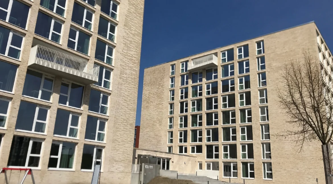
Brick cladding is one of the most widely used façade systems in commercial and residential construction. When properly designed and installed, it offers durability, thermal performance, and architectural appeal. The structural integrity of any brick cladding system, however, depends on one critical component: the restraint system.
Masonry and brick cladding restraints are the fixings, ties, and channels that anchor the outer leaf of brickwork to the building’s structural substrate. Without a reliable system, external walls are vulnerable to wind loading, thermal movement, and long-term structural instability. This guide provides a technical overview of the key restraint systems, their specifications, design requirements, and installation considerations, offering a practical reference for specifying and installing compliant cladding systems efficiently.
What Are Brick Cladding Restraints?
Brick cladding restraints are structural components designed to connect the outer skin of a masonry wall to the inner load-bearing structure. Their primary function is to resist horizontal loads—particularly wind pressure and suction—while allowing for controlled vertical and thermal movement in the cladding.
As specified in BS EN 845-1: 2003 (Specification for Ancillary Components for Masonry), wall ties must meet specific performance requirements for interconnecting masonry leaves and connecting masonry to structural elements. Restraint ties must absorb a tensile force of 1 kN with a maximum slip of 1 mm per tie—a threshold that directly informs product selection and spacing on site.
Types of Brick Cladding Restraint Systems
Several distinct restraint systems are available, each engineered for specific structural configurations and performance requirements.
Brickwork Restraint Channels (HMP)
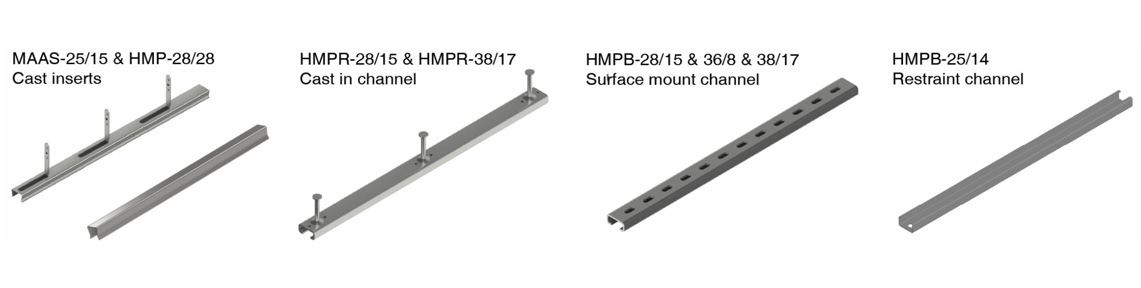
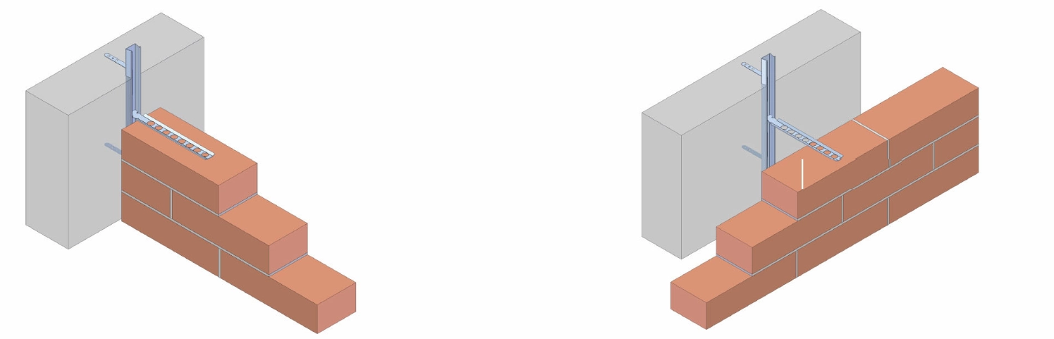
HMP Brickwork Restraint Channels are used with compatible wall ties to restrain the outer brickwork skin. A key advantage is installation flexibility: wall ties can be positioned anywhere along the channel’s length, simplifying installation and allowing for minor positional adjustments on site.
Allowable pull-out loads for HMP channels range from 1.2 kN to 4.5 kN at a tie distance of 250 mm, depending on the channel type, making them suitable for a range of façade heights and wind load conditions.
Restraining Ties (HRST)
HRST Restraining Ties are specifically designed to restrain outer shell brickwork walls against horizontal loads. They are available in versions compatible with both brickwork and concrete load-bearing walls, offering versatility across different structural substrates.
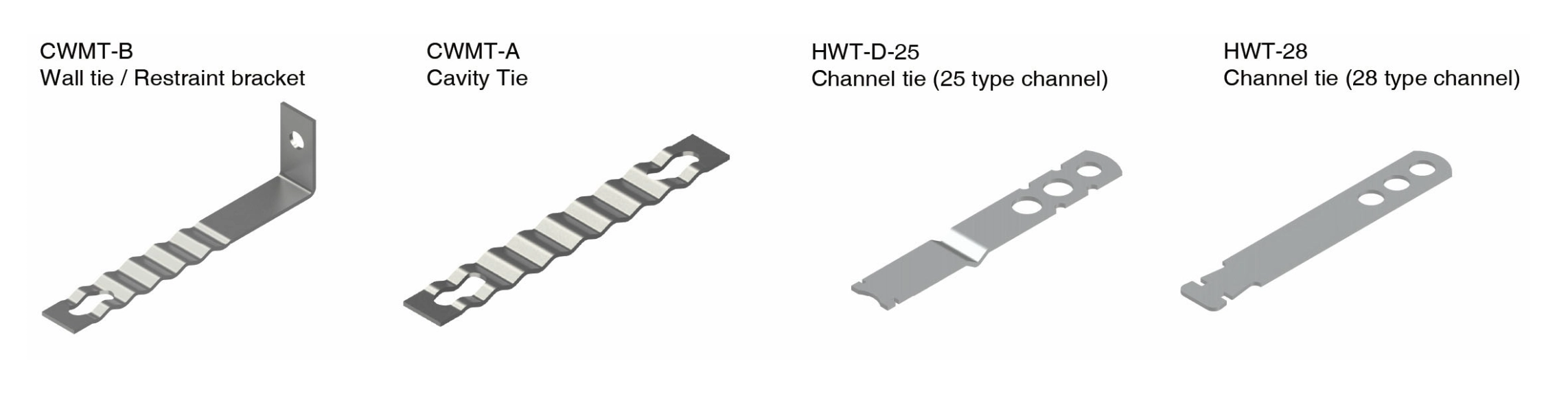
Brickwork Wall Ties (CMWT)
The CMWT range of corrugated wall ties provides lateral restraint for wind pressure and suction. Available in four configurations (CMWT-A, CMWT-B, CMWT-C, and CMWT-D), these ties connect brick walls to reinforced concrete walls or metal studs.
Performance specifications vary: CMWT-D has a tensile loading of 0.7 kN per 600 mm screw centers, while CMWT-C achieves 1.0 kN. Selecting the correct variant depends on cavity width, substrate type, and the calculated wind load for the project.
Special Restraint Channels (HMS-AV)
The HMS-AV Special Restraint Channel is designed for brick wall claddings positioned in front of flat reinforced concrete rooftops subject to deformation. Used with HWT-M wall ties, this system accommodates differential movement between the cladding and the substrate—an important consideration where structural deflection is anticipated.
Brick Restraint System (HMP-25/14)
The HMP-25/14 system ties back the outer leaf brick cladding wall to the building substrate, with wind load capacities from 1.58 to 3.31 kN/m² depending on tie type, building height, and location. Pre-drilled holes at 100 mm spacing allow for screw attachment through insulation.
This system is also well-suited for connecting brickwork to steel studding, a common configuration in lightweight framed construction.
Head Restraints (HMHR)
HMHR Brickwork Head Restraints address the challenge of restraining brickwork below horizontal soft joints while permitting differential vertical movement. These fixings attach the brickwork to the structure while allowing movement at the interface, with a service load rating of 1 kN.
Head restraints are a critical component where vertical movement joints are incorporated at floor slab levels, preventing the cladding from being loaded by structural deflection.
Key Design Requirements
Correct system selection is only one part of a successful installation. The design and detailing of the overall system must comply with applicable standards and account for structural and environmental variables.
Applicable Standards
Design of brickwork support and restraint systems should reference the following standards:
- BS EN 1996 – Design of masonry structures
- BS EN 1990 – Basis of structural design
- BS EN 1991 – Actions on structures
- BS EN 1993 – Design of steel structures
- BS EN 1998 – Design for earthquake resistance
- BS 5628-1: 2005 – Code of Practice for the Use of Masonry
Tie Spacing Requirements
Tie spacing is a critical installation parameter. The vertical distance between restraining ties must not exceed 450 mm, and the horizontal distance must not exceed 900 mm. At free edges—including building corners, expansion joints, and openings—three restraining ties must be provided per metre of edge length, in addition to standard spacing.
Height and Thickness Limits
Outer brickwork shells supported by restraint systems can reach a maximum height of 12 metres. The minimum thickness of the outer leaf must be 90 mm. These parameters are non-negotiable and must be confirmed before installation.
Expansion Joints
Expansion joints are essential for the long-term performance of brick cladding, accommodating both structural movement and thermal expansion. Without adequate provision for movement, the outer leaf is at risk of cracking.
Horizontal joints are positioned at each supporting level. Vertical expansion joints are governed by climatic loads and material type; generally, connected brickwork walls in corner areas should not exceed 7–14 metres in width. All expansion joints must be filled with suitable compressible material and sealed to maintain weathertightness.
Materials and Durability
Restraint fixings for brick cladding are typically manufactured from durable austenitic stainless steel. Grade 1.4301 (AISI 304) is used in most applications, while Grade 1.4401 (AISI 316) is specified for more corrosive environments, such as coastal locations.
Galvanized mild steel is also used, though stainless steel remains the preferred material for longevity and corrosion resistance. Specifying the correct material grade is essential to achieving the intended design life and ensuring long-term reliability.
Installation Best Practices
Even a well-specified restraint system can underperform if installation is poorly executed. These practical guidelines apply across most system types to ensure project efficiency:
- Embed ties properly: Wall ties must achieve a minimum embedment of 50 mm in each masonry leaf. Ties should be pressed into fresh mortar, fully surrounded, and installed with a slight fall toward the outer leaf to prevent water ingress.
- Install ties during construction: Cavity wall ties should be installed as the inner leaf is built, not pushed into joints retroactively. This ensures correct embedment and structural engagement.
- Follow channel fixing procedures: For HMP-type channels, insert ties into the slot and rotate 90 degrees to lock them in place before applying mortar.
- Account for insulation: Tie length must be sufficient to bridge the full cavity width, including insulation, while still achieving the required embedment.
Getting Brick Cladding Restraints Right
Masonry and brick cladding restraints are fundamental to the structural performance and durability of a façade system. Selecting the appropriate tie or channel, designing to current standards, and following correct installation procedures are all non-negotiable steps in delivering a compliant, high-performance cladding system.
The range of systems available means there is a reliable solution for virtually every structural configuration. The key is matching the right product to the specific demands of the project: substrate type, cavity width, building height, wind loading, and expected movement.
For complex façade designs or projects requiring bespoke fixing solutions, working with a façade engineering specialist ensures all technical parameters are met in line with applicable codes and standards.